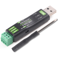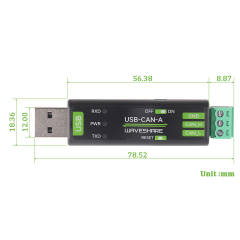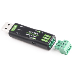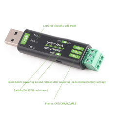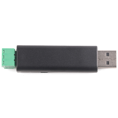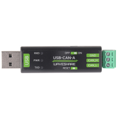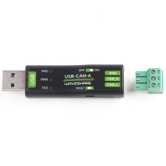
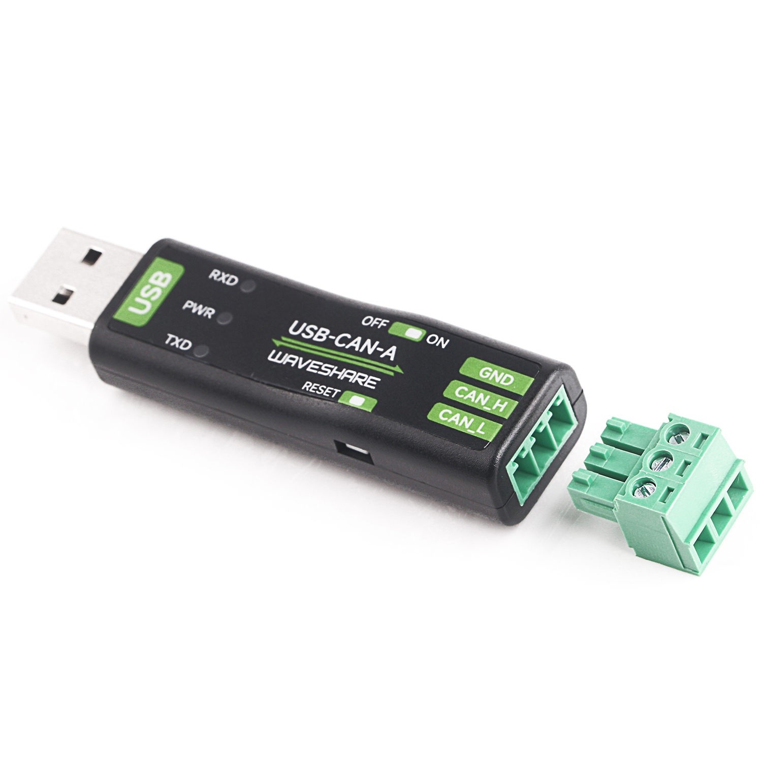
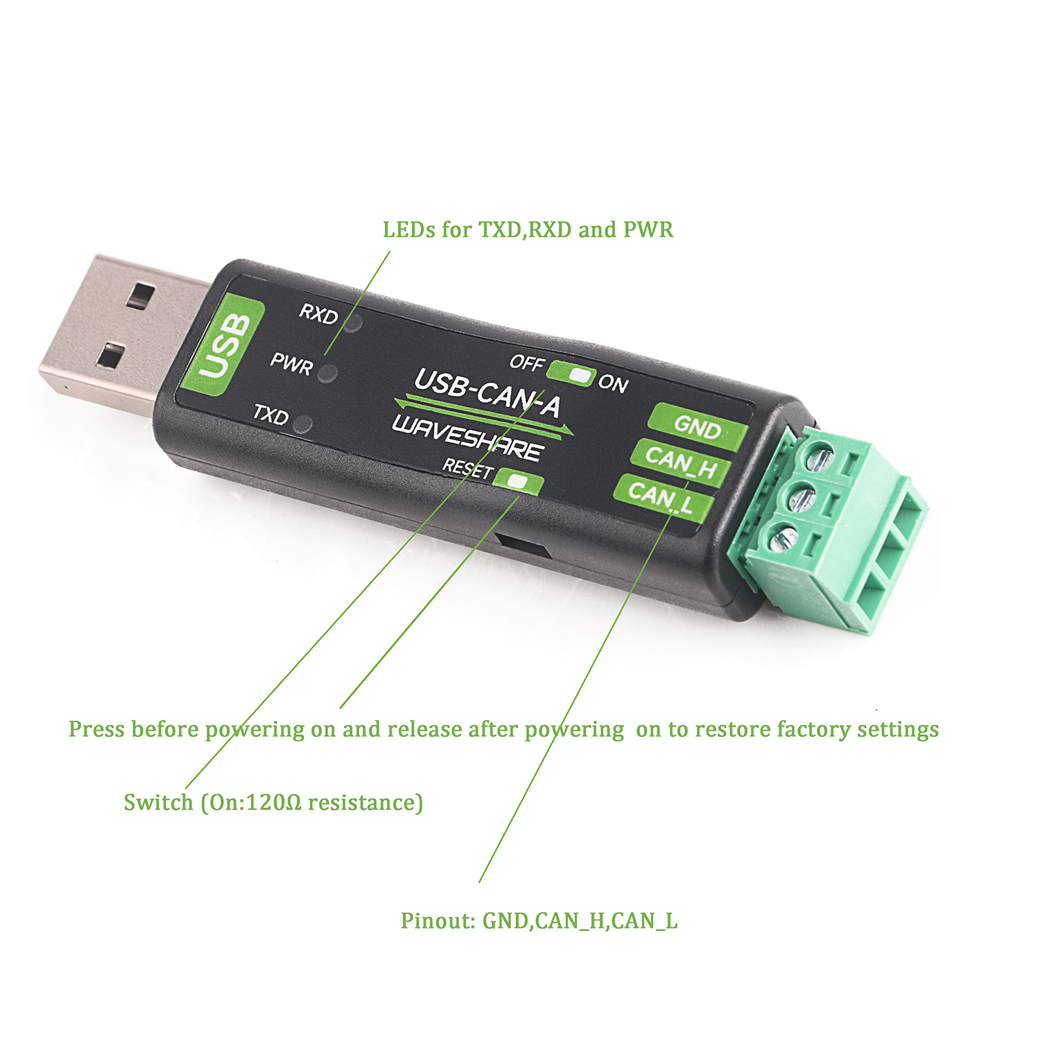
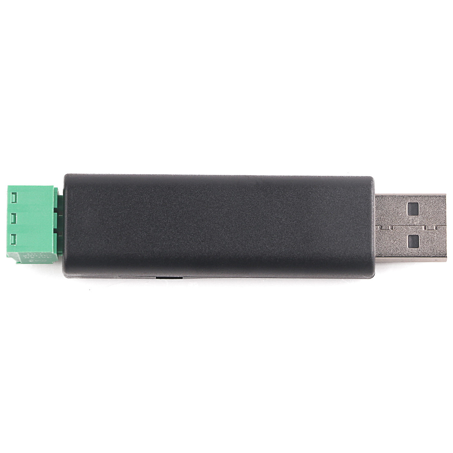
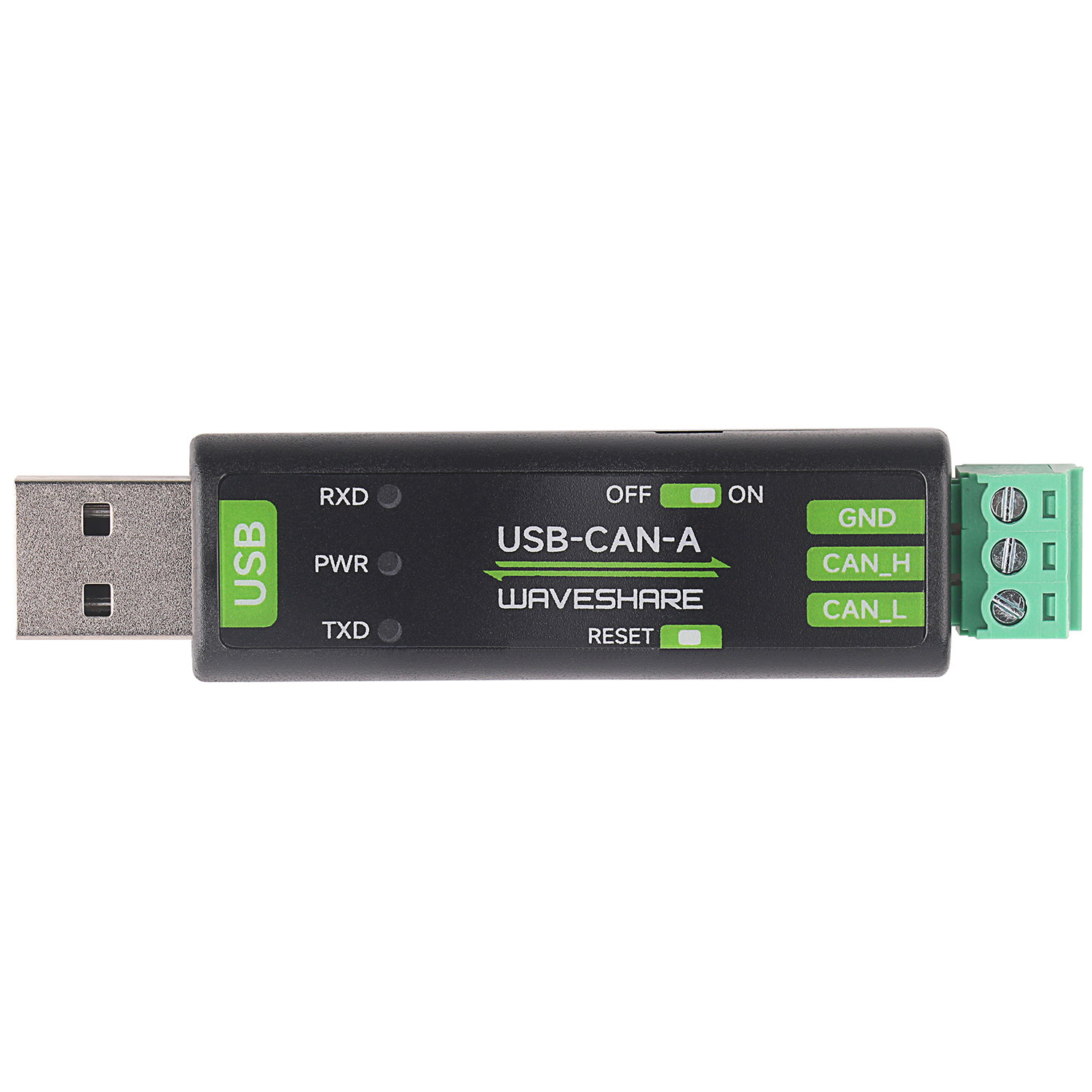

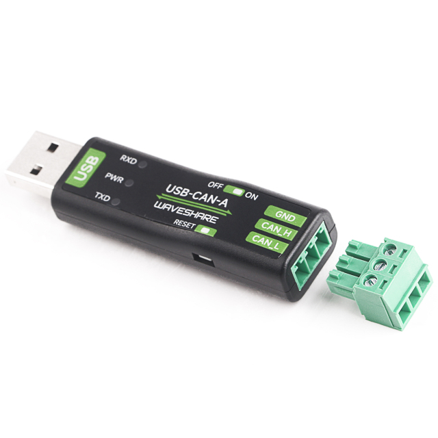


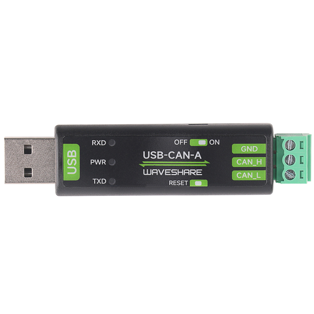
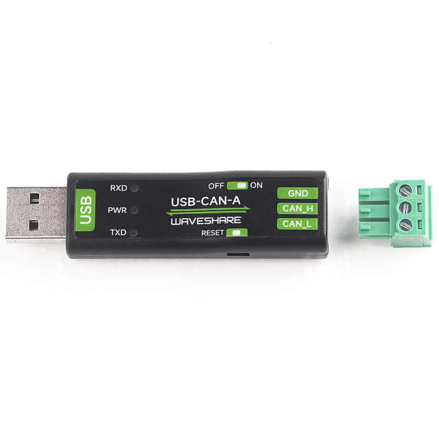
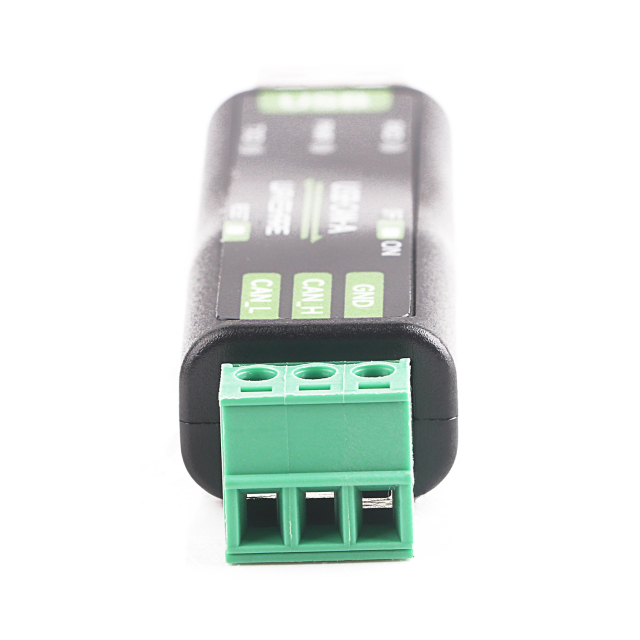
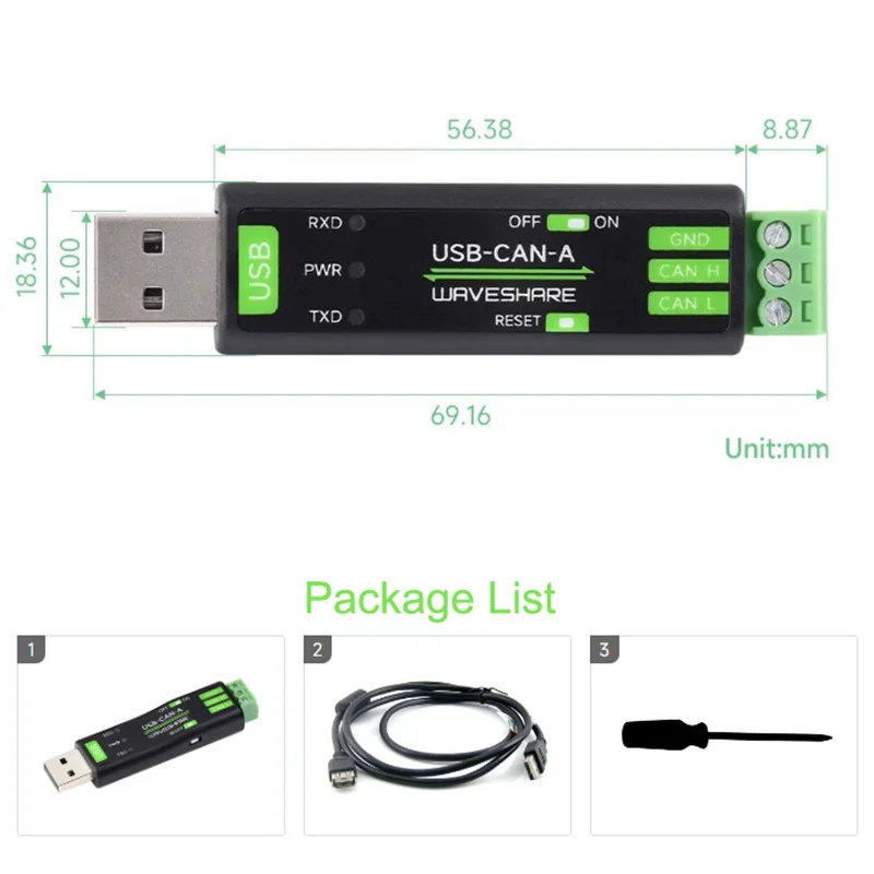
Product Features:
1. Support CAN2.0A (standard frame) and CAN2.0B (extended frame)
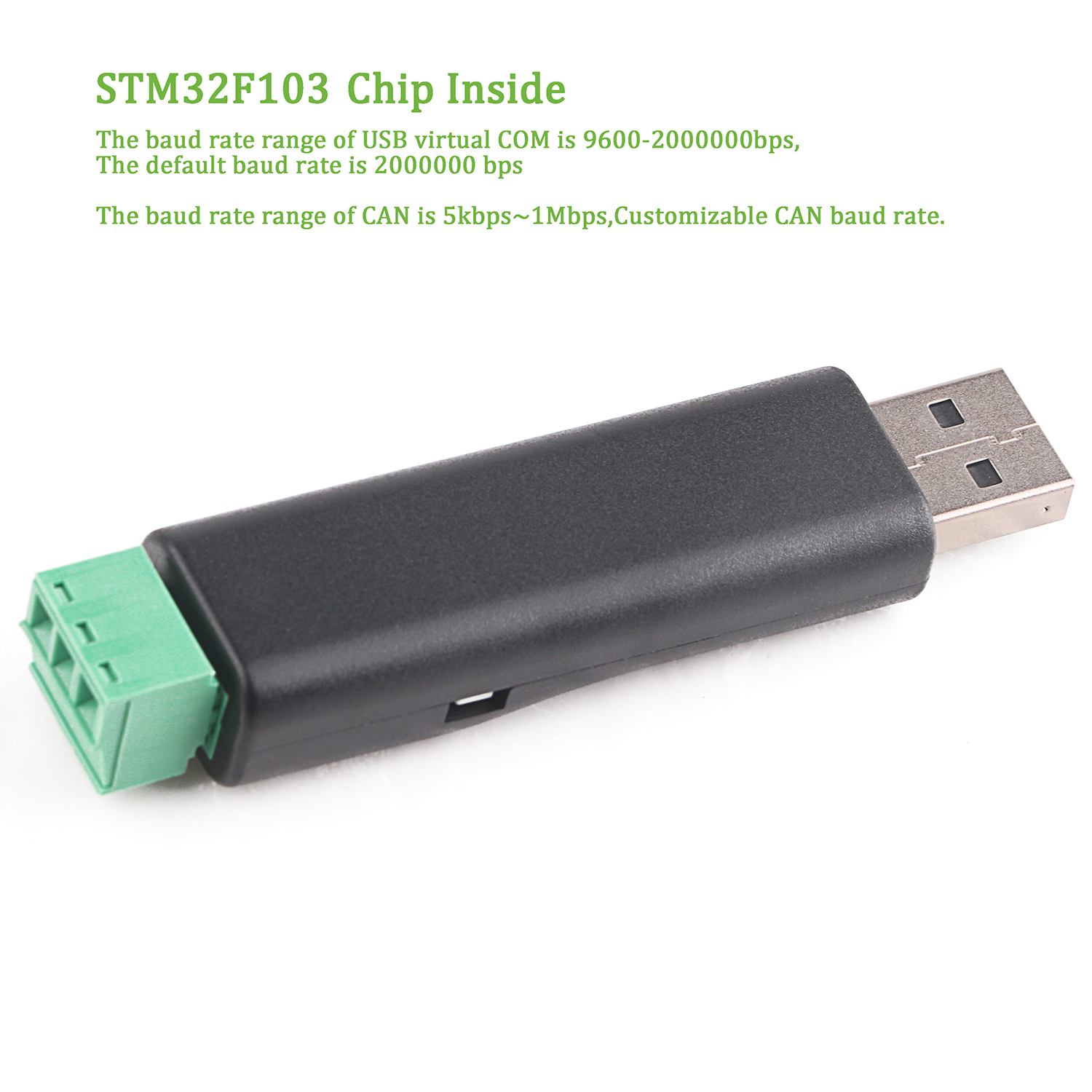
2. Supports CAN communication baud rate range: 5kbps~1Mbps, CAN baud rate can be customized
3. Supports four working modes: normal mode, loopback mode, silent mode, silent loopback mode
4. Supports multiple CAN data sending methods: single frame sending, multi-frame sending, manual sending, scheduled sending and cycle sending
5. Supports multiple CAN data receiving methods: it can be configured to only receive data with a specified ID, or it can also specify an ID to automatically respond to the configured data.
6. Supports sending and receiving CAN data saved as TXT or EXCEL text
7. Supports CAN bus detection, making it easy to check the CAN bus status
8. CAN sending and receiving data are displayed with time stamps, which can be displayed sequentially or refreshed.
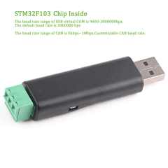
9. Supports setting the communication baud rate of the USB virtual COM port (9600 ~ 2000000bps), the default is 2000000bps
10. Supports setting working parameters through configuration software or serial port instructions, and can be saved when power is turned off
11. Using STM32 imported chip solution, communication is stable and reliable
12. Onboard TVS (transient voltage suppressor) effectively suppresses surge voltage and transient peak voltage of the circuit
13. Provide Windows version of PC software in Chinese and English, easy to use
14. Supports secondary development, only needs to process sending and receiving commands
Download the CH341SER driver , double-click the CH341SER.EXE file, and click Install. When the driver installation is successful, click OK to complete the driver installation:
The tool requires no installation. After downloading and decompressing the file, open the USB-CAN.exe file:

① Port setting area:
After inserting the USB to CAN converter into the computer, you can automatically find the computer COM port. Select the port and you can open or close the port. This is similar to the serial port debugging assistant. The default communication baud rate is 2000000bps.
Some serial port assistants (taking the underlying hex data) may not have 2M. If you need to change the small baud rate, please refer to the following: Instructions for changing the COM (232) baud rate: 1. Plug in the converter with a USB data cable, and pay attention to sending and The acceptance indicator light flashes several times at the same time:
Flash 1 time, the baud rate of the corresponding serial port is 2000000bps. Flash 2 times, the baud rate of the corresponding serial port is 1228800bps. Flash 3 times, the baud rate of the corresponding serial port is 115200bps. Flash 4 times, and the baud rate of the corresponding serial port is 38400bps. Flash 5 times. Flash 6 times , the baud rate of the corresponding serial port is 19200bps. Flash 6 times, the baud rate of the corresponding serial port is 9600bps.
2. Open the software, select the corresponding COM port number and baud rate, and click the Open button (for example, when the converter is plugged into the USB data line and powered on, if the transceiver indicator light flashes 1 time at the same time, we should select the baud rate of 2000000bps) 3. Click to
open Button
4. Click the Change Baud Rate button, and a dialog box will pop up. After we select the baud rate we want to set in the Baud Rate combo box, click Change; if you do not want to change, click the Cancel button.
5. For example, we want to set the baud rate to 9600bps:
In the baud rate combo box is 9600.
Click the change button and pay attention to the flashing of the converter's transmit and receive indicator lights.
Corresponding to the 9600 baud rate converter, the sending and receiving indicators will flash 6 times at the same time.
Since the port baud rate has been changed, you need to close the port and reopen it by selecting the changed baud rate.
6. Click the Close button
7. Select the baud rate as the changed baud rate
8. Click the Open button again
② CAN setting area:
working modes include normal mode, loopback mode, silent mode, loopback and silent mode
Normal mode: It is the normal communication mode of CAN, which can send and receive data to the bus normally.
Loopback mode: The sent data can be sent to the CAN bus, and the internal receiving area is fed back at the same time, ignoring the actual state of the receiving pin, which can be used for self-testing
Silent mode: Data can be received normally, but only recessive bits can be sent, but messages cannot actually be sent. It is often used to analyze CAN bus activity.
Loopback silent mode: This mode can be used for "hot self-test", that is, online self-test. Self-testing is possible like loopback mode, but does not affect the CAN bus system.
Frame type: Standard frame (CAN2.0A 11-bit ID) Extended frame (CAN2.0B 29-bit ID)
CAN baud rate: You can directly select the commonly used baud rate for CAN communication: 1M, 800K, 500K, 400K, 250K, 200K, 125K, 100K, 50K, 20K, 10K, 5K; if the baud rate that can be directly set above is the same as The baud rate of your CAN device is inconsistent and can be selected.
Filter ID and shielding ID: both are hexadecimal data. The lower 11 bits of the filter ID and shielding ID are valid in the standard frame (range: 0x00000000~0x000007ff), and the lower 29 bits of the extended frame filter ID and shielding ID are valid (range 0x00000000~0x1fffffff)
Fixed 20-byte transceiver: There are two conversion protocols inside the CAN converter. One is a communication protocol with variable length, and the other is a fixed 20-byte communication protocol. When selected, it will be a fixed 20-byte communication protocol. If not selected, it will be a fixed 20-byte communication protocol. After selecting the variable protocol communication, a dialog box for customizing the baud rate will pop up. At the top is the calculation formula of the CAN baud rate, and at the same time set the phase buffer 1, phase buffer 2, and prescaler.
Disable automatic re-transmission of messages: CAN communication generally automatically re-transmits failed messages. If you keep sending data in a loop, you can set it to prohibit automatic re-transmission of messages. Click Settings and Start to start CAN communication.
③ Send single frame data area:
The frame format includes data frames and remote frames. The frame ID is hexadecimal data. For standard frames, the frame ID range is 0x00000000~0x000007fff. For extended frames, the frame ID range is 0x00000000~0x1fffffff. The data sent is also hexadecimal data. The data in the picture are 0x11 0x22 0x33 0x44 0x55 0x66 0x77 0x88. Click the Send Single Frame button to send the frame data to the CAN bus.
④ Multi-frame sending data area:
Add button: A piece of sending frame data will be added below the selected line in the sending multi-frame area
Delete button: will delete the selected row
Clear button: will clear all data in the multi-frame sending area
Interval time: The interval between sending two consecutive frames in the multi-frame sending area (milliseconds)
Send selected frame: Click this button to send the selected line in the multi-frame area.
Sequence: After selecting, click Send and the selected frame will automatically switch to the next frame.
Loop: After selecting, click Send and the selected frame will be sent in a loop.
Stop: Cancel sending multi-frame command
⑤ Automatic answering area:
Add button: An automatic reply data will be added below the selected line in the automatic reply area
Delete button: will delete the selected row
Clear button: All data in the automatic answering area will be cleared
Automatic response: When selected, the received ID will be automatically replied to the corresponding frame ID and data.
⑥ CAN bus status area:
mainly used to view the CAN communication status of the USB to CAN device
⑦ Configuration acceptance ID area:
Add button: An automatic response data will be added below the selected line in the configuration acceptance area. Delete button: The selected line will be deleted. Enable button: After clicking this button, the converter will only upload the ID set in the configuration acceptance ID area. Do not upload other IDs to the computer. Disable the button: After clicking this button, the converter will upload all ID data to the computer.
⑧ Transmitting and receiving data display area:
Clear: Clear all data in the sending and receiving data display
Pause: Pause to display other data in the sending and receiving display area
Continue: continue to display sending and receiving data
Save: The data in the sending and receiving data buffer can be saved in two formats, excel or txt text.
Do not display the sending frame: you can only display the received data in the sending and receiving data area
Automatic refresh: When only the accepted data is displayed, you can choose automatic refresh. At this time, the data is refreshed in real time instead of continuously adding column display. This function can summarize the ID data summarized by CAN and select any row.